
Tilt System Assembly
15003 Tilt Brake Disc (Removal and Replacement)
Correction Code : 15003 Working Hours : 0.5H
NOTE:
Unless otherwise explicitly stated in the procedure, the above correction code and Working Hours
reflect all of the work required to perform this procedure, including the linked procedures.
Do not stack correction codes unless explicitly told to do so.
Remove
Step 1
Place vehicle on level surface with enough room to tilt to full limits in either direction.
Step 2
Remove the tilt brake caliper (ref. Gaius Procedure: 15001)
15001 Tilt Brake Caliper (Removal and Replacement)
Step 3
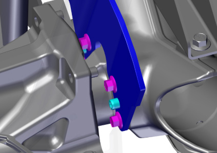
Remove tilt brake disk from vehicle
- remove existing M8 bolts from the tilt brake disc using a box-end wrench or
spanner. This may require use of a breaker bar to break bolts free. - remove old split pins (press out or pry out with vice-grips).
Step 4
Clean and degrease surfaces between tilt disc and rear chassis.
Step 5
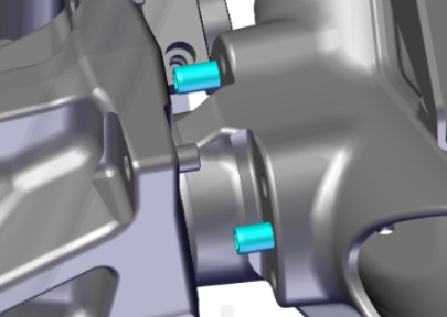
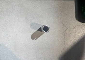
Insert/set new split pins into tilt disc. Pins should be installed with the open groove down to minimize water accumulation.
Step 6
Mate tilt disc to rear chassis, aligning split pins with holes. Press in split pins using a leverage bar to force in the pins.
Step 7
Install new bolts:
- Apply a few drops of medium-strength threadlocker (Loctite 243 or equivalent) to the new bolts. Bolt
specification is M8-1.25 Gr 10.9 x 20mm length. - Insert bolt into disc hole and hand tighten
- Repeat for all four (4) fasteners
- Torque bolts to 30 Nm using crowfoot torque wrench following a diagonal torque sequence (per image ).
Note, this may require tilting vehicle to allow rotation on torque wrench.
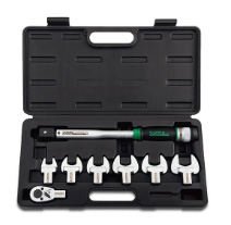
The special tools required are shown in the figure on the left.
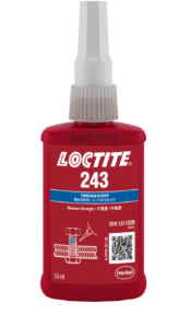
Medium Strength Threadlocker (Loctite 243 or equivalent)
Step 8
Mark all joints using indelible paint pen (green to indicate field repair).
Step 9
Recycle/Discard old hardware.